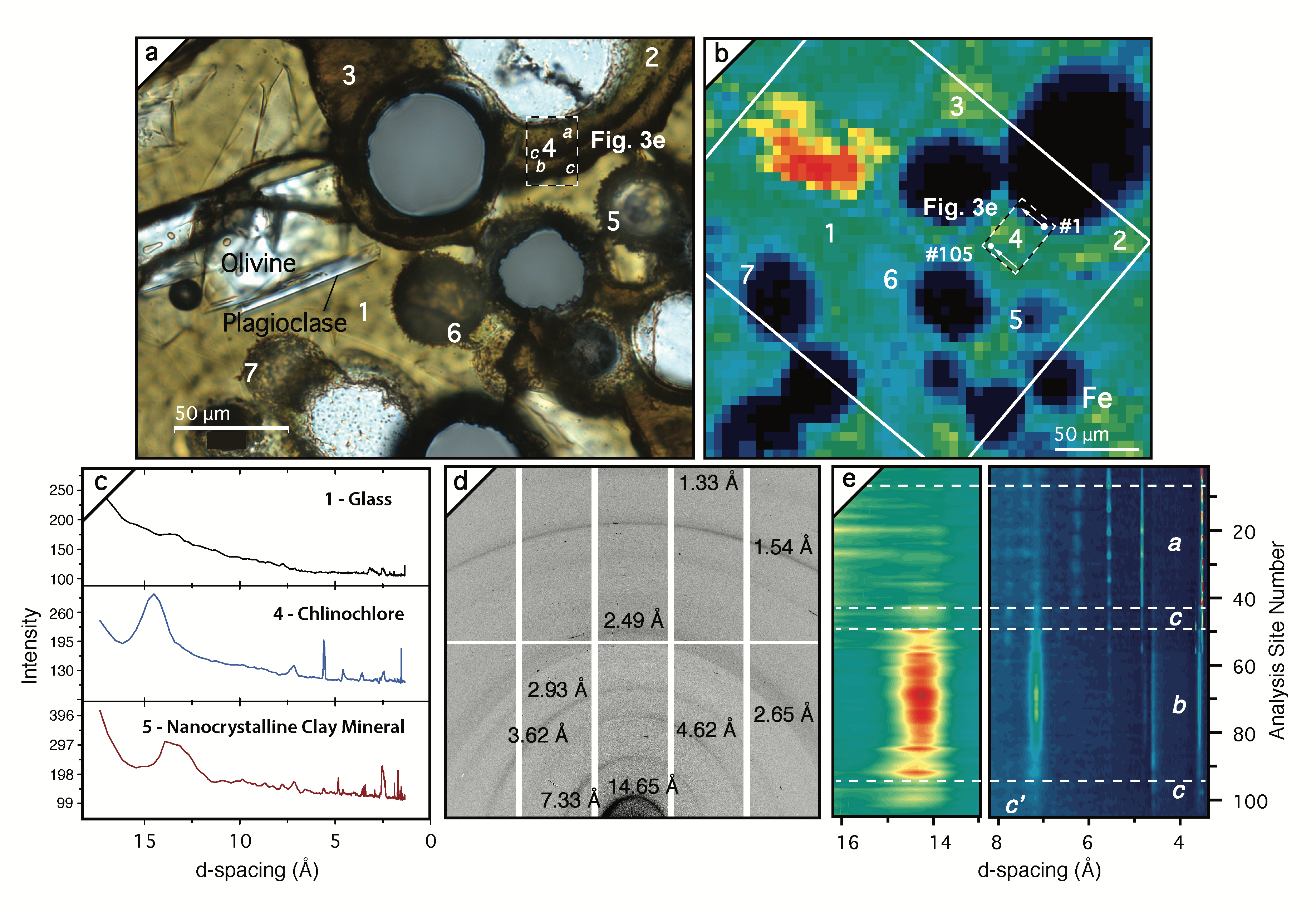
Authigenic Mineral Texture in Submarine 1979 Basalt Drill Core, Surtsey Volcano, Iceland
The thermal, chemical, and mineralogical evolution of basaltic rocks and the physical properties Earth’s oceanic and continental crust are fundamentally linked. To better understand the evolution of basalt alteration over short geologic timescales, we turn to a newly formed volcanic island, Surtsey, in southern Iceland. The analyzed samples are composed of glassy basaltic fragments, created by explosive interactions between magma and seawater. They come from drill core collected in 1979, which was still hot when acquired 15 years after the eruptions ceased. The research focuses on (1) the alteration of the basaltic glass into secondary minerals and (2) tiny linear features formed of concentrically oriented secondary minerals. The partial dissolution of glass and its rapid transformation to clay mineral frees constituents that crystallize as zeolite and Al‐tobermorite mineral cements. The linear features are composed of clay minerals (nontronite) and zeolite (amicite). Organic carbon‐rich matter is associated with their clay mineral layers. These structures differ, however, from those in microtunnels ascribed to biologic activity in older basaltic rocks. The analyses provide a stepping stone toward understanding the earliest basaltic alteration in oceanic environments. Overall, our study demonstrates that basaltic and thereby crustal evolution is a more fast‐paced, dynamic process than previously thought.
These are the scientists who contributed to this article and their professional affiliations.
M. D. Jackson 1 , S. Couper 1, C. V. Stan 2 , M. Ivarsson 3,4, M. W. Czabaj 5, N. Tamura 6,
D. Parkinson 6, L. M. Miyagi 1, and J. G. Moore 7
1Department of Geology and Geophysics, University of Utah, Salt Lake City, UT, USA(m.d.jackson@utah.edu),
2NIF and Photon Science, Livermore National Laboratory, Livermore, CA, USA,
3Department of Biology and Nordic Center for Earth Evolution, University of Southern Denmark, Odense, Denmark, 4Department of Palaeobiology, Swedish Museum of Natural History, Stockholm, Sweden,
5Department of Mechanical Engineering, University of Utah, Salt Lake City, UT, USA,
6Advanced Light Source, Lawrence Berkeley National Laboratory, Berkeley, CA, USA,
7U.S. Geological Survey, Menlo Park, CA, USA